9.5 KiB
9.5 KiB
🌟LilyGo T-Beam🌟
Overview
- This page introduces the hardware parameters related to
LilyGo T-Beam
Notes on use
- Please be sure to connect the antenna before transmitting, otherwise it is easy to damage the RF module
Product
| Product | SOC | Flash | PSRAM |
|---|---|---|---|
| T-Beam Meshtastic | ESP32-D0WDQ6-V3 | 4MB(Quad-SPI) | 8MB(Quad-SPI) |
| T-Beam SoftRF | ESP32-D0WDQ6-V3 | 4MB(Quad-SPI) | 8MB(Quad-SPI) |
PlatformIO Quick Start
- Install the CH9102 USB bridge driver for the first time.
- Install Visual Studio Code and Python
- Search for the
PlatformIOplugin in theVisual Studio Codeextension and install it. - After the installation is complete, you need to restart
Visual Studio Code - After restarting
Visual Studio Code, selectFilein the upper left corner ofVisual Studio Code->Open Folder-> select theLilyGo-LoRa-Seriesdirectory - Wait for the installation of third-party dependent libraries to complete
- Click on the
platformio.inifile, and in theplatformiocolumn - Select the board name you want to use in
default_envsand uncomment it. - Uncomment one of the lines
src_dir = xxxxto make sure only one line works , Please note the example comments, indicating what works and what does not. - Click the (✔) symbol in the lower left corner to compile
- Connect the board to the computer USB-C , Micro-USB is used for module firmware upgrade
- Click (→) to upload firmware
- Click (plug symbol) to monitor serial output
- If it cannot be written, or the USB device keeps flashing, please check the FAQ below
Arduino IDE quick start
-
Install the CH9102 USB bridge driver for the first time.
-
Install Arduino IDE
-
Install Arduino ESP32
-
Copy all folders in the
libdirectory to theSketchbook locationdirectory. How to find the location of your own libraries, please see here- Windows:
C:\Users\{username}\Documents\Arduino - macOS:
/Users/{username}/Documents/Arduino - Linux:
/home/{username}/Arduino
- Windows:
-
Open the corresponding example
- Open the downloaded
LilyGo-LoRa-Series - Open
examples - Select the sample file and open the file ending with
ino
- Open the downloaded
-
On Arduino Select the corresponding board in the IDE tool project and click on the corresponding option in the list below to select
Name Value Board ESP32 Dev Module Port Your port CPU Frequency 240MHZ(WiFi/BT) Core Debug Level None Erase All Flash Before Sketch Upload Disable Events Run On Core1 Flash Frequency 80MHZ Flash Mode QIO Flash Size 4MB(32Mb) JTAG Adapter Disabled Arduino Runs On Core1 Partition Scheme Huge APP (3MB No OTA/1MB SPIFFS) PSRAM Enable Upload Speed 921600 Programmer Esptool -
Please uncomment the
utilities.hfile of each sketch according to your board model ,e.gT_BEAM_SX1262,T_BEAM_SX1276,T_BEAM_SX1278, otherwise the compilation will report an error. -
Upload sketch
📍 Pins Map
| Name | GPIO NUM | Free |
|---|---|---|
| SDA | 21 | ❌ |
| SCL | 22 | ❌ |
| OLED(SSD1306) SDA | Share with I2C bus | ❌ |
| OLED(SSD1306) SCL | Share with I2C bus | ❌ |
| GNSS(Ublox M6/M8) TX | 12 | ❌ |
| GNSS(Ublox M6/M8) RX | 34 | ❌ |
| LoRa(SX1276/SX1278) SCK | 5 | ❌ |
| LoRa(SX1276/SX1278) MISO | 19 | ❌ |
| LoRa(SX1276/SX1278) MOSI | 27 | ❌ |
| LoRa(SX1276/SX1278) RESET | 23 | ❌ |
| LoRa(SX1276/SX1278) DIO1 | 33 | ❌ |
| LoRa(SX1276/SX1278) DIO2 | 32 | ❌ |
| LoRa(SX1276/SX1278) CS | 18 | ❌ |
| Button1 | 38 | ❌ |
| PMU (AXP2101) IRQ | 35 | ❌ |
| PMU (AXP2101) SDA | Share with I2C bus | ❌ |
| PMU (AXP2101) SCL | Share with I2C bus | ❌ |
🧑🏼🔧 I2C Devices Address
| Devices | 7-Bit Address | Share Bus |
|---|---|---|
| OLED Display (SSD1306) | 0x3C | ✅️ |
| Power Manager (AXP2101) | 0x34 | ❌ |
⚡ Electrical parameters
| Features | Details |
|---|---|
| 🔗USB-C Input Voltage | 3.9V-6V |
| ⚡Charge Current | 0-1024mA (Programmable) |
| 🔋Battery Voltage | 3.7V |
⚡ PowerManage Channel
| Channel | Peripherals |
|---|---|
| DC1 | ESP32 |
| DC2 | Unused |
| DC3 | Unused |
| DC4 | Unused |
| DC5 | Unused |
| LDO1(VRTC) | Unused |
| ALDO1 | Unused |
| ALDO2 | Radio |
| ALDO3 | GPS |
| ALDO4 | Unused |
| BLDO1 | Unused |
| BLDO2 | Unused |
| DLDO1 | Unused |
| CPUSLDO | Unused |
| VBACKUP | GNSS Backup |
Button Description
| Channel | Peripherals |
|---|---|
| PWR | PMU button, customizable function |
| IO38 | Customizable function |
| RST | Reset button |
- The PWR button is connected to the PMU
- In shutdown mode, press the PWR button to turn on the power supply
- In power-on mode, press the PWR button for 6 seconds (default time) to turn off the power supply
LED Description
-
CHG LED
- If not controlled by the program, the default is always on when charging and off when fully charged
- This LED can be controlled by the program
-
PPS LED,
- The red LED near the GPS module cannot be turned off
- This LED cannot be turned off and is connected to the GPS PPS Pin. This LED flashes to indicate that the PPS pulse has arrived.
RF parameters
| Features | Details |
|---|---|
| RF Module | SX1278/SX1276 |
| Frequency range | 868/915MHz |
| Transfer rate(LoRa) | 0.018 K ~ 62.5 Kbps |
| Transfer rate(FSK) | 0.6 K ~ 300 Kbps |
| Modulation | FSK, GFSK, MSK, GMSK, LoRa,OOK |
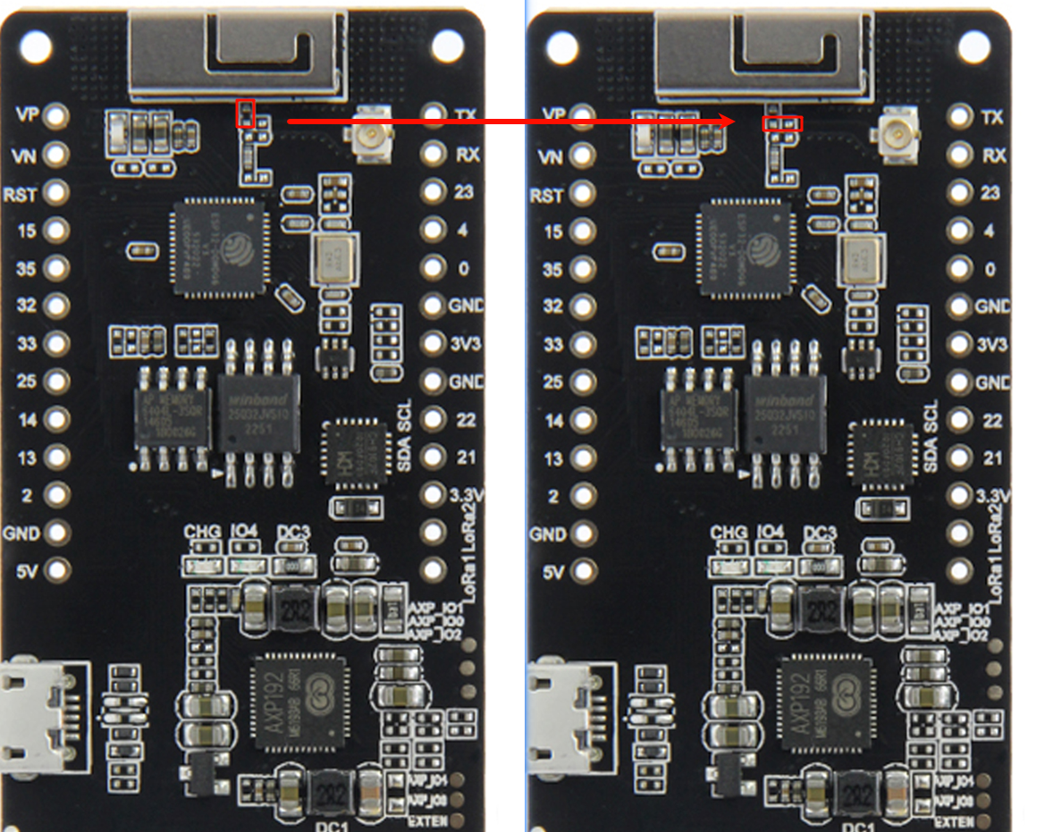
WiFi-IPEX
- The following figure shows how to switch the onboard WIFI antenna to IPEX