6.1 KiB
Exercise 21 — Six-Axis IMU Characterization
Overview
Exercise 21 establishes a foundational understanding of the six-axis inertial measurement unit (IMU) on the T-Beam Supreme. The IMU (QMI8658) provides:
- Accelerometer (X, Y, Z) — measures acceleration, including gravity
- Gyroscope (X, Y, Z) — measures angular velocity
This exercise focuses on interpreting accelerometer data to determine device orientation relative to gravity.
Objective
The goals of this exercise are:
- Demonstrate that IMU outputs are frame-dependent but physically consistent
- Show that startup orientation does not define the IMU axes
- Compute roll and pitch from raw accelerometer data
- Quantify real-world deviations from ideal values
- Identify sources of measurement error
Test Setup
Two static orientations of the device were evaluated:
Orientation A — Sideways
Device resting on its side (edge of AlleyCat case)
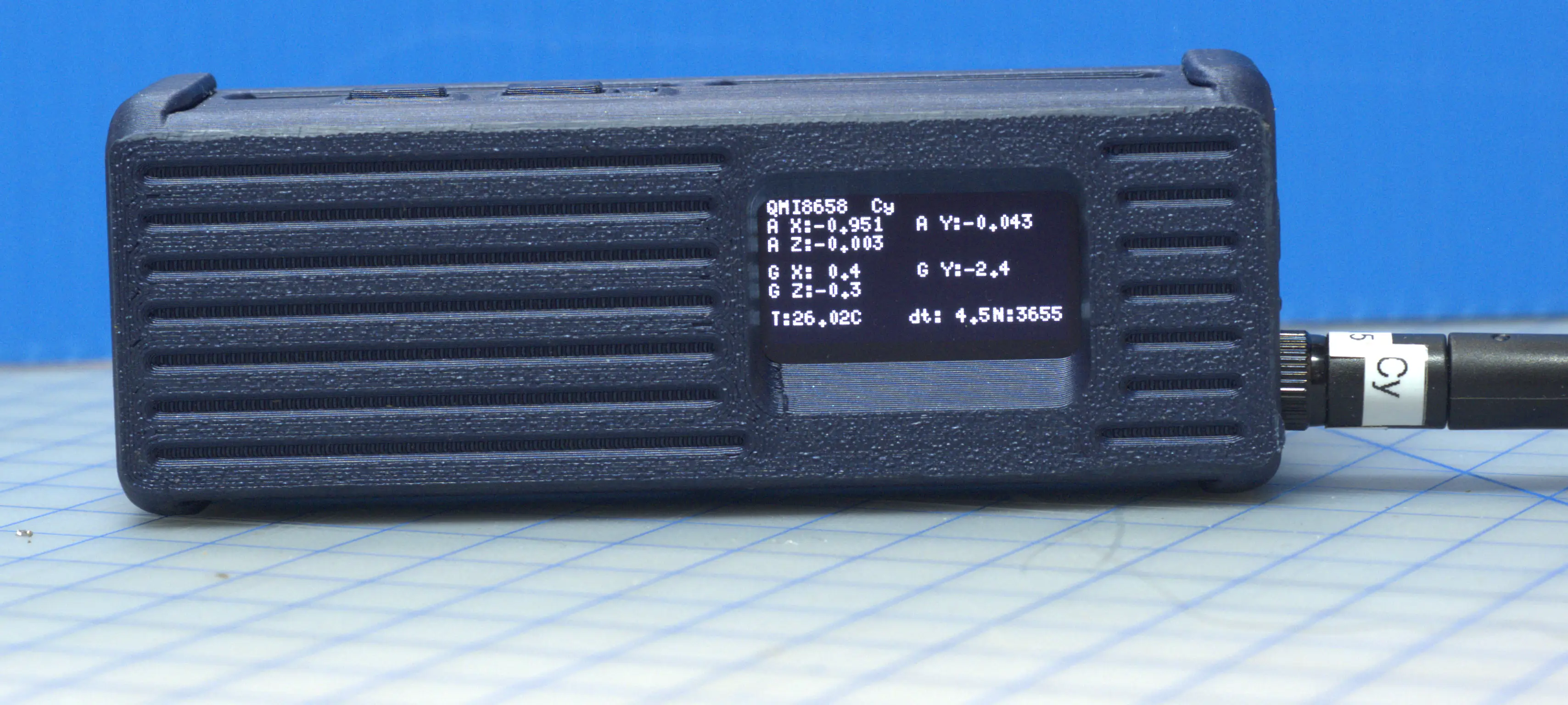
Measured accelerometer values:
Ax = -0.951
Ay = -0.043
Az = -0.003
Orientation B — Upright
Device standing upright (antenna vertical)
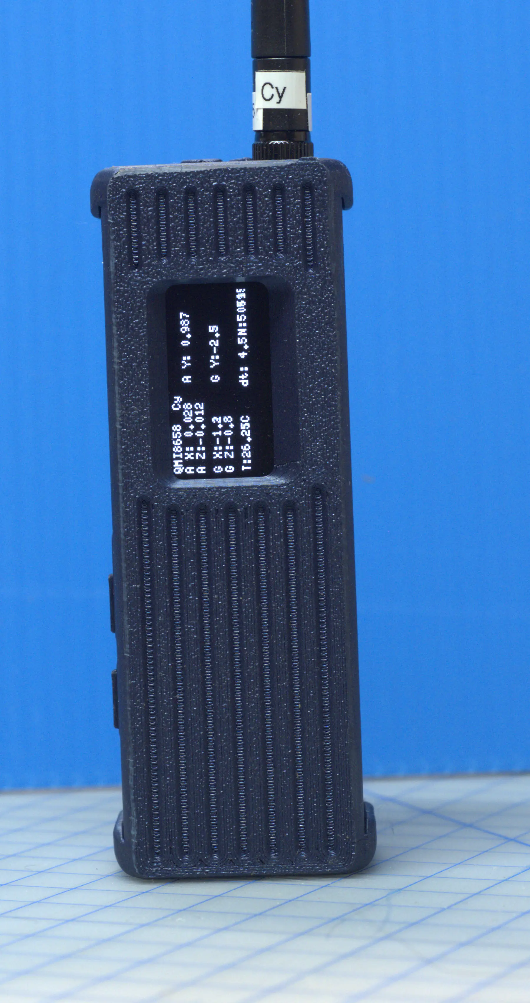
Measured accelerometer values:
Ax =  0.028
Ay =  0.987
Az =  0.012
Methodology
Roll and pitch were computed using standard inertial navigation formulas:
roll  = atan2(Az, Ay)
pitch = atan2(-Ax, sqrt(Ay² + Az²))
These equations derive orientation from the gravity vector projection onto the sensor axes.
Implementation
A Perl script was used to compute roll and pitch:
scripts/imu_roll_pitch_demo.pl
This script:
- Accepts predefined accelerometer values
- Computes roll and pitch in radians and degrees
- Uses Perl’s built-in
atan2()for accurate quadrant handling
Results
Sideways Orientation
roll  = -176.009°
pitch =  87.405°
Interpretation:
- Pitch ≈ 90° → confirms device is rotated onto its side
- Roll near ±180° is expected due to sign conventions when vertical
Upright Orientation
roll  =  0.697°
pitch = -1.625°
Interpretation:
- Both values near 0° → device is nearly level
- Small deviations indicate real-world imperfections
Key Findings
1. IMU Axes Are Fixed
The IMU coordinate system is defined by the sensor hardware and PCB layout:
- It does not change at startup
- It is independent of how the device is oriented when powered on
2. Orientation Is Derived from Gravity
The accelerometer measures the gravity vector:
- Different orientations produce different raw values
- The underlying physics is consistent
3. Roll and Pitch Are Orientation-Invariant
While raw values differ between orientations:
- Computed roll/pitch reflect true physical orientation
- Results are consistent regardless of startup pose
4. Coordinate Mapping
From the observed accelerometer data:
- Upright orientation: +Y_sensor ≈ UP
- Sideways orientation: -X_sensor ≈ UP (after 90° rotation)
We define a device coordinate system aligned with the AlleyCat enclosure:
- Z_device = UP (antenna direction)
- Y_device = FORWARD (normal to display, pointing outward)
- X_device = RIGHT (along the long axis of the display)
Mapping from sensor frame to device frame:
Z_device = +Y_sensor
The remaining axes are determined by physical orientation and require sign validation:
X_device ≈ +Z_sensor
Y_device ≈ ±X_sensor
Final sign conventions should be verified empirically by observing motion:
- Rotate device forward/back → affects Y_device
- Rotate device left/right → affects X_device
This mapping separates:
- Sensor frame (hardware-defined)
- Device frame (application-defined)
and provides a consistent basis for roll, pitch, and future magnetometer integration.
Sources of Error
The observed deviations (~1–2°) are expected and arise from several factors:
Surface Imperfection
- Table or support surface not perfectly level
- Enclosure geometry (AlleyCat case) introduces tilt
Sensor Bias (Offset)
- Example: Ax ≠ 0 when it should be
- Typical of MEMS sensors
Scale Error
Measured magnitude:
|A| ≈ 0.988 g (ideal = 1.000 g)
Indicates slight gain inaccuracy.
Axis Misalignment
- Sensor axes are not perfectly orthogonal
- Manufacturing tolerances introduce small angular errors
Noise and Quantization
- Finite precision (3 decimal places)
- Minor fluctuations expected
Limitations of Exercise 21
This exercise deliberately omits several important elements:
No Absolute Heading
- Without a magnetometer, yaw (heading) is undefined
- Only roll and pitch can be determined
No Sensor Fusion
- Gyroscope data is not integrated
- No filtering (e.g., complementary or Kalman)
No Calibration
- Raw sensor values are used directly
- Bias and scale errors are uncorrected
Static Analysis Only
- No dynamic motion analysis
- Gyroscope output not utilized
Significance
Exercise 21 provides a critical baseline:
- Confirms correct IMU operation
- Establishes device coordinate frame
- Demonstrates physical interpretation of accelerometer data
- Quantifies real-world sensor error
This forms the foundation for:
- Magnetometer integration (Exercise 22)
- Tilt-compensated compass
- Full sensor fusion (AHRS)
Conclusion
The IMU behaves as expected:
- Raw outputs vary with orientation
- Derived angles correctly reflect physical pose
- Measured errors are consistent with typical MEMS performance
Most importantly:
The IMU does not define orientation — it measures vectors.
Orientation is derived through mathematical interpretation of those vectors.
Next Steps
Exercise 22 will extend this work by introducing:
- Magnetometer (QMC6310)
- Absolute heading (yaw)
- Tilt compensation using roll and pitch
References
- Perl Script:
scripts/imu_roll_pitch_demo.pl - Images:
img/upright_DSC_5194.webpimg/sideways_DSC_5195.webp