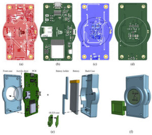
<p class="wp-block-paragraph">A light meter project that measures sunlight in a similar way that a rain gauge measure rainfall caught my interest. I’ve been trying to measure how much sunlight my orchids receive in the greenhouse during low sun months in Salem, OR. The project is a paper published in <em>Electronics</em> titled “<a href="https://www.mdpi.com/2079-9292/14/11/2225">Open-Source Photosynthetically Active Radiation Sensor for Enhanced Agricultural and Agrivoltaics Monitori<em>ng</em></a>.” The authors created a portable light meter and designed the circuit board with a special sensor. They claim the cost of the parts is about $70 (USD). An equivalent professional unit (and one with higher tolerances) costs about $490.</p>
<p><img class="alignnone size-medium wp-image-354" src="https://salemdata.net/johnpress/wp-content/uploads/2025/11/electronics-14-02225-g005-550-300×266.jpg" alt="" width="300" height="266" /></p>
<p>The printed circuit board (“PCB”) was design in a program called KiCad, the authors used version 8.1 I have KiCad 9.0.5. In Kicad, you have various layers and can design circuits, silkscreen masks, drill holes &etc. When you are ready to create your circuit board, you export the project into a series of Gerber files which are instructions for various machines to fabricate the circuit board and possibly assemble it using a robot. Each file controls a particular action such as etching copper traces, cutting the board to a shape, printing silkscreen labels, drilling holes &etc.</p>
<p>The problem I faced is that I contacted the authors saying I wanted to order from a PCB manufacturer some boards and build them. They responded that the design they released in April of 2025 has since been modified to correct some design flaws they discovered during their soldering process, so, for me, they updated the file November 20, 2025. They also provided another set of Gerber files exported from the updated KiCad file, but one of the files was defective, so I opened their revised KiCad project and re-exported the defective file.</p>
<p>There were two issues I faced: 1) what were the changes they made and how do I visualize them, and 2) will my KiCad version 9.0.5 faithfully export Gerber files that match their KiCad version 8.1. This arena of exporting Gerber files from a particular version of KiCad is extremely complicated and a version change of software can introduce problem that you do not discover until after the boards are printed. I’ve read it takes several iterations of printing circuit boards to work our the bugs. I do not want to have to go through the time-consuming and expensive process of producing five or more versions of the board.</p>
<p>So, to help me visualize what changes there were between their April release, their November release, and my export, I created a tool which overlays visual renditions of each Gerber file, each layer having a red, blue, or green color and then seeing where things do not align. Sure enough, the copper traces on the front side of the circuit board had been changed:</p>
<p><img class="alignnone wp-image-352 size-full" src="https://salemdata.net/johnpress/wp-content/uploads/2025/11/20251122_185853_Sat.png" alt="" width="1454" height="914" /></p>
<p>The above screenshot displays the differences. Where everything matches goes white or black. where there are differences are color coded: red = April version, blue = November version. If mine varied from the other two, there would be green. If everything matches, the three blue, green, and red colors blend into white.<br /><br />There are about 10 Gerber files for each export, so with three differing versions, there would be 3 sets of 10 files to compare, it would take a couple of hours just to load the individual files into the program Gerbv[iewer], then set the color and opacity. With ChatGPT, I created a Perl script that does all of that so all I have to do is point to the three directories containing the Gerber exports and my Perl scripts will launch Gerbv and will create 10 SVG [scalable vector graphics] files and then an HTML page to display them. Here is a PDF of the 10 images: <a href="https://salemdata.net/johnpress/wp-content/uploads/2025/11/Gerber-Comparison-Results-20251122_194254.pdf">Gerber Comparison Results – 20251122_194254</a></p>
A light meter project that measures sunlight in a similar way that a rain gauge measure rainfall caught my interest. I’ve been trying to measure how much sunlight my orchids receive in the greenhouse during low sun months in Salem, OR. The project is a paper published in Electronics titled “Open-Source Photosynthetically Active Radiation Sensor for Enhanced Agricultural and Agrivoltaics Monitoring.” The authors created a portable light meter and designed the circuit board with a special sensor. They claim the cost of the parts is about $70 (USD). An equivalent professional unit (and one with higher tolerances) costs about $490.
The printed circuit board (“PCB”) was design in a program called KiCad, the authors used version 8.1 I have KiCad 9.0.5. In Kicad, you have various layers and can design circuits, silkscreen masks, drill holes &etc. When you are ready to create your circuit board, you export the project into a series of Gerber files which are instructions for various machines to fabricate the circuit board and possibly assemble it using a robot. Each file controls a particular action such as etching copper traces, cutting the board to a shape, printing silkscreen labels, drilling holes &etc.
The problem I faced is that I contacted the authors saying I wanted to order from a PCB manufacturer some boards and build them. They responded that the design they released in April of 2025 has since been modified to correct some design flaws they discovered during their soldering process, so, for me, they updated the file November 20, 2025. They also provided another set of Gerber files exported from the updated KiCad file, but one of the files was defective, so I opened their revised KiCad project and re-exported the defective file.
There were two issues I faced: 1) what were the changes they made and how do I visualize them, and 2) will my KiCad version 9.0.5 faithfully export Gerber files that match their KiCad version 8.1. This arena of exporting Gerber files from a particular version of KiCad is extremely complicated and a version change of software can introduce problem that you do not discover until after the boards are printed. I’ve read it takes several iterations of printing circuit boards to work our the bugs. I do not want to have to go through the time-consuming and expensive process of producing five or more versions of the board.
So, to help me visualize what changes there were between their April release, their November release, and my export, I created a tool which overlays visual renditions of each Gerber file, each layer having a red, blue, or green color and then seeing where things do not align. Sure enough, the copper traces on the front side of the circuit board had been changed:
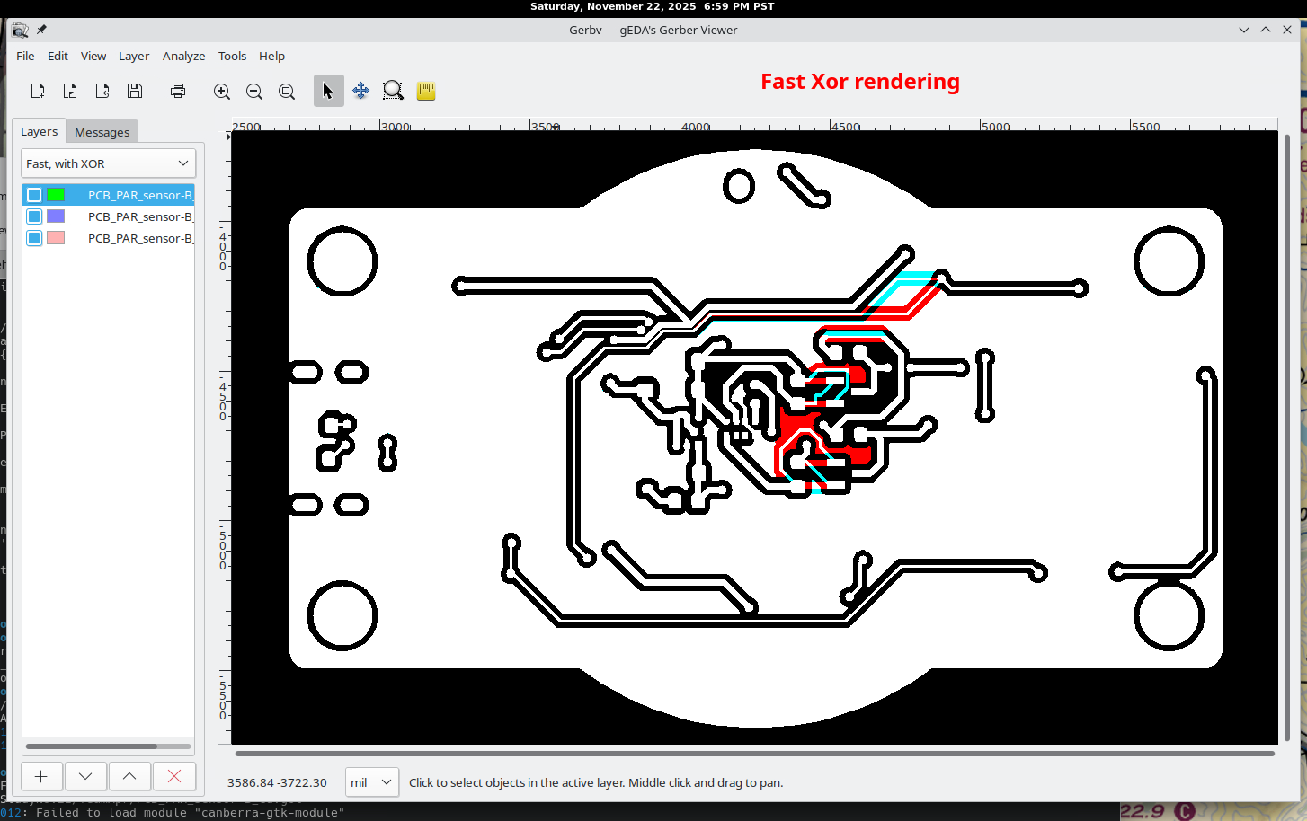
The above screenshot displays the differences. Where everything matches goes white or black. where there are differences are color coded: red = April version, blue = November version. If mine varied from the other two, there would be green. If everything matches, the three blue, green, and red colors blend into white.
There are about 10 Gerber files for each export, so with three differing versions, there would be 3 sets of 10 files to compare, it would take a couple of hours just to load the individual files into the program Gerbv[iewer], then set the color and opacity. With ChatGPT, I created a Perl script that does all of that so all I have to do is point to the three directories containing the Gerber exports and my Perl scripts will launch Gerbv and will create 10 SVG [scalable vector graphics] files and then an HTML page to display them. Here is a PDF of the 10 images: Gerber Comparison Results – 20251122_194254
Leave a Reply