<p class="wp-block-paragraph">Designing a decibel monitor by combining a $15 <a href="https://www.raspberrypi.com/products/raspberry-pi-zero-2-w/">Raspberry Pi Zero 2 W </a>computer with the<a href="https://pcbartists.com/product/i2c-decibel-sound-level-meter-module/"> PCB Artists Decibel Module</a> board should be easy. But that’s not how I do things.</p>
<p class="wp-block-paragraph">I want the unit to have a button that allows the user to power down the unit gracefully. If someone just pulls the plug, then there is a risk that the disk will become corrupted. It is preferable to have the use depress a button for 3 seconds so the unit knows to power down gracefully without risk of data corruption. </p>
<p class="wp-block-paragraph">I like the idea of the button displaying different colors through LEDs for different states, e.g. “shutting down”, “Connected to network”, “Not Connected to network”, blinking red when loud aircraft go overhead. So I am adding an <a href="https://www.adafruit.com/product/3425">RGB LED momentary push button</a>. </p>
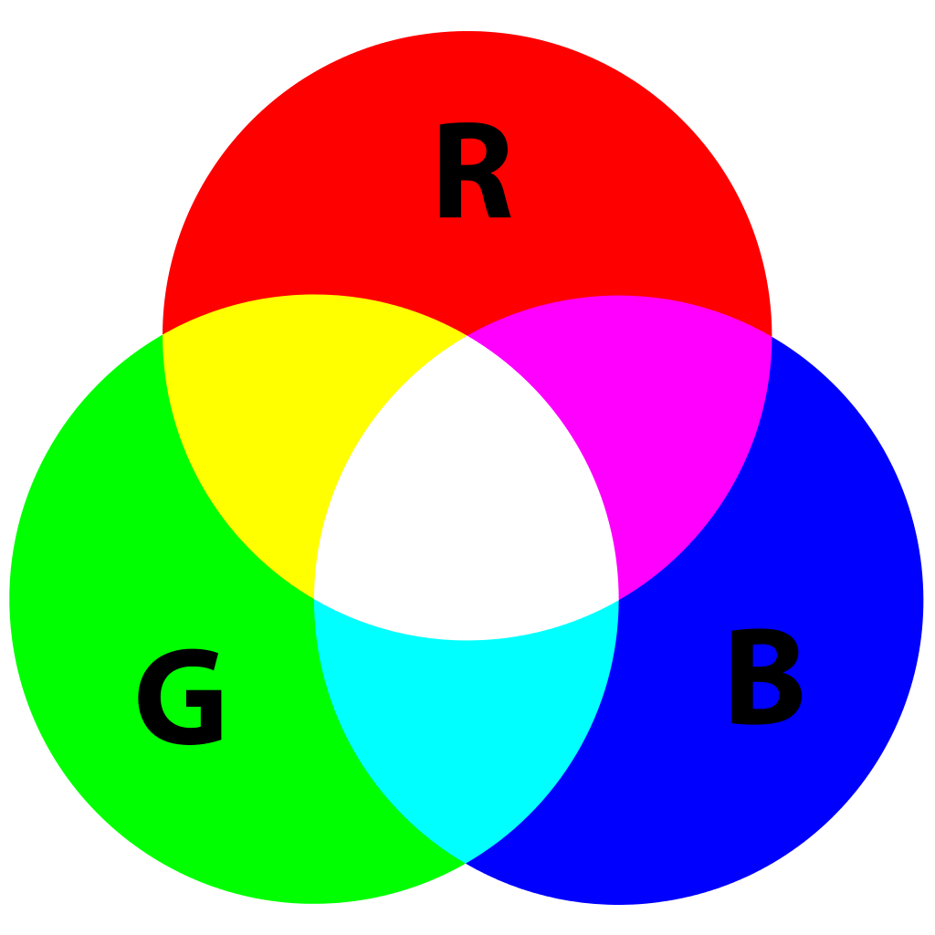
<p class="wp-block-paragraph"> RGB stands for “Red Green Blue” and consists of three light emitting diodes of those three primary colors which can be manipulated to create any color of the spectrum. Remember the primary color diagram where mixing the three primary colors produces “white” and red + green = yellow?</p>
<figure class="wp-block-image size-full wp-duotone-unset-2"><img src="https://salemdata.net/johnpress/wp-content/uploads/2024/04/RGB_diagram.png" alt="" class="wp-image-100"/></figure>
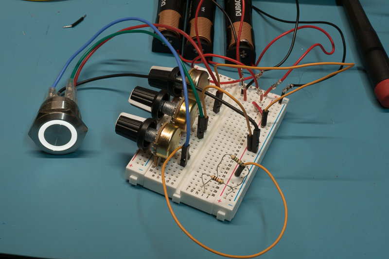
<p class="wp-block-paragraph">Here’s a picture of a breadboard with an RGB LED momentary push button hooked up to it. I’m using variable resistors (aka <a href="https://en.wikipedia.org/wiki/Potentiometer">potentiometers </a>with knobs) to alter the current sent to each color channel with the goal of creating the right mix to produce a “white” light. Here I did so and after powering down, measured the resistance of each potentiometer so I have a recipe to make the button appear white.</p>
<figure class="wp-block-image size-full wp-duotone-unset-3"><img src="https://salemdata.net/johnpress/wp-content/uploads/2024/04/DSC_3859.jpg" alt="" class="wp-image-101"/></figure>
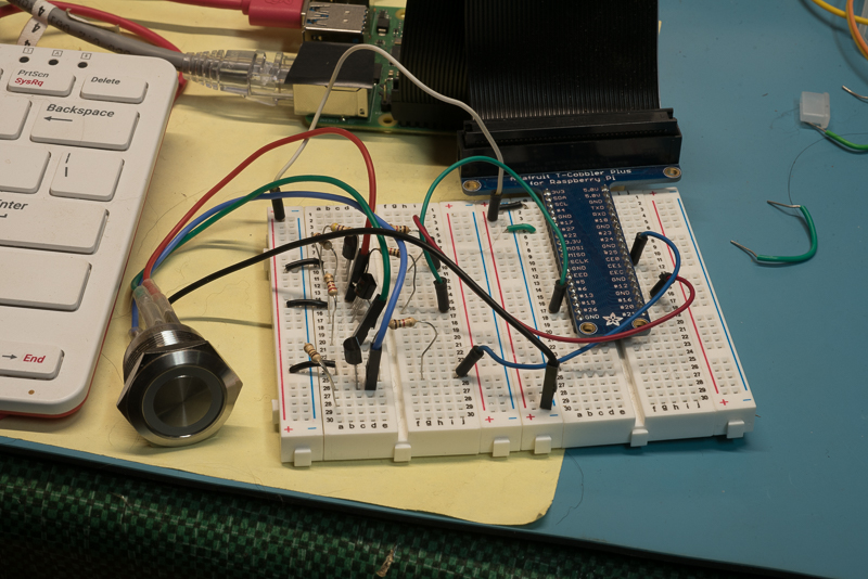
<p class="wp-block-paragraph">I can cause the Raspberry Pi computer to send different signals to each color channel and that allows me to mix the three to make any possible color. Here’s a photo of another breadboard where the Raspberry Pi computer is controlling the circuit. (The light is off.)</p>
<figure class="wp-block-image size-full wp-duotone-unset-4"><img src="https://salemdata.net/johnpress/wp-content/uploads/2024/04/DSC_3890.jpg" alt="" class="wp-image-102"/></figure>
<p class="wp-block-paragraph">As you can see above in the breadboards: it gets messy. That’s why a printed circuit board serves a purpose — it organizes the rat’s nest of wires and doesn’t have loose wires. </p>
<p class="wp-block-paragraph">Including an RGB LED switch adds to the complexity of the project and necessitates adding 3 transistors to protect the Raspberry Pi’s Input/Output pin from being flooded with too much current lighting the LEDs. Also, connecting securely the Decibel Monitor utilizing <a href="https://en.wikipedia.org/wiki/JST_connector">Japan Solderless Terminals </a>(“JST”) connectors necessitate having a circuit board for the mating part. In addition, since the case is inside a closed polycarbonate box, I’d want to have a temperature sensor to make sure the limit of 170 °F is not reached because Raspberry Pi board will then shut down. Simple projects get complicated… quickly.</p>
<p class="wp-block-paragraph"><a href="http://kicard.org">KiCad </a>is an open source “electronics design automation suite” which translated lets you design printed circuit boards, aka “PCB”s. You then send your design to a manufacturer who sends you the PCB. My needs are very simple:</p>
<ul class="wp-block-list">
<li>JST receptable for Decibel Monitor</li>
<li>JST receptable for RGB LED</li>
<li>Transistor hub for Temperature Sensor</li>
</ul>
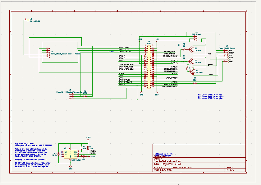
<p class="wp-block-paragraph">Here are the two workbenches one uses in KiCad. First, the schematics diagram which inventories the parts and uses “wires” to determine what gets connected to what.</p>
<figure class="wp-block-image size-full wp-duotone-unset-5"><img src="https://salemdata.net/johnpress/wp-content/uploads/2024/04/tvnviewer_2024-04-07_20-22-14.png" alt="" class="wp-image-98"/></figure>
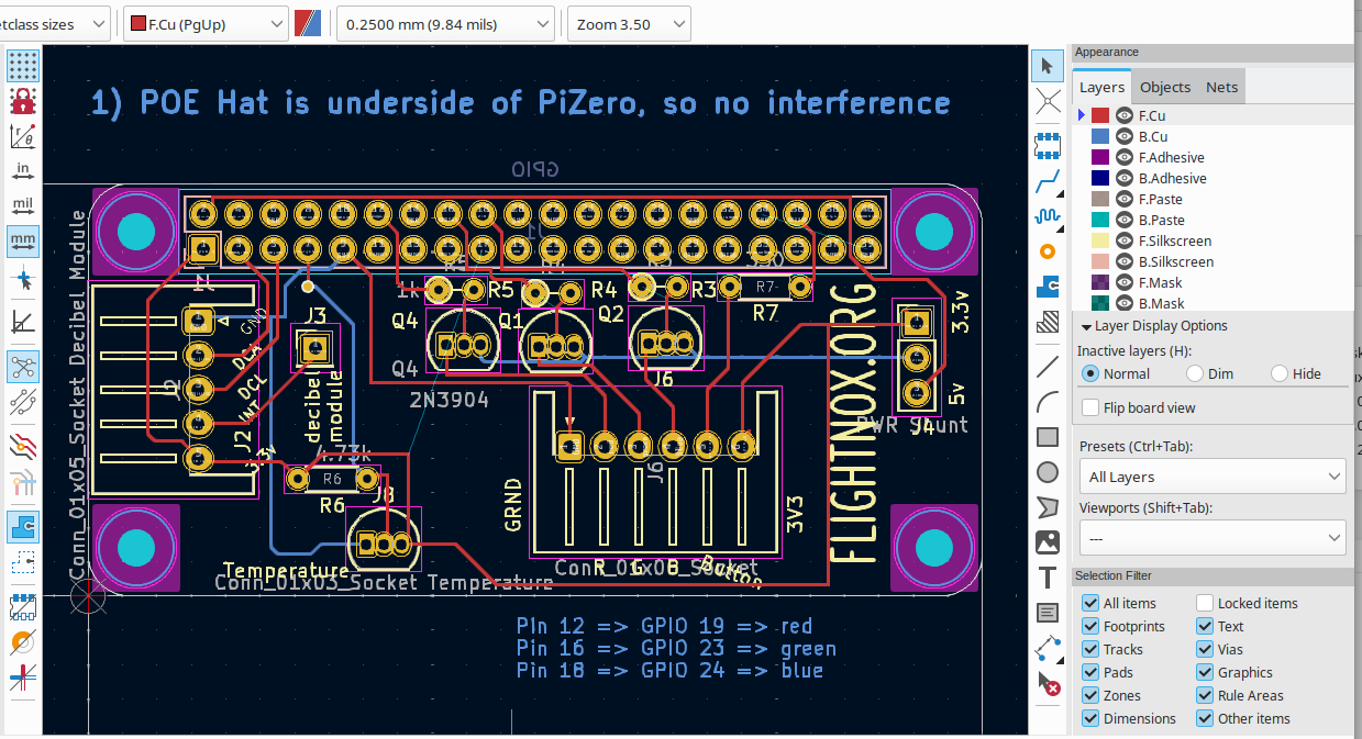
<p class="wp-block-paragraph">Second, after you have defined all the components in the schematics pane and tied everything together, you then define what the PCB will look like and can moved component around and then make “traces” which are copper lines or foil.</p>
<figure class="wp-block-image size-full wp-duotone-unset-6"><img src="https://salemdata.net/johnpress/wp-content/uploads/2024/04/tvnviewer_2024-04-07_20-21-33.png" alt="" class="wp-image-99"/></figure>
<p class="wp-block-paragraph">Here is a 3d representation of the board as it exists on April 7, 2024. <strong>You can use your mouse by depressing it over the PCB </strong>to rotate or twirl it so you can peek at its back side, the image below is really a 3 dimensional viewer that you can manipulate.</p>
<iframe width="640" height="480" style="border:1px solid #eeeeee;" src="https://salemdata.us/3dviewer/embed.html#model=https://salemdata.us/models/decibel_uhat.wrl$camera=0.14770,-0.08618,0.09748,0.13250,-0.08500,0.00077,0.00000,1.00000,0.00000,45.00000$projectionmode=perspective$envsettings=fishermans_bastion,off$backgroundcolor=255,255,255,255$defaultcolor=200,200,200$defaultlinecolor=100,100,100$edgesettings=off,0,0,0,1"></iframe>
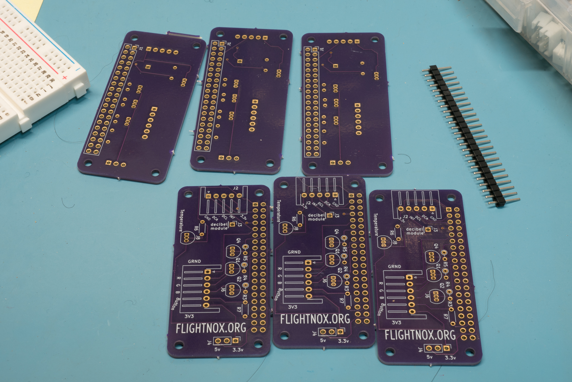
<p class="wp-block-paragraph">I’m going to use a “fab house” [printed circuit board<strong> fab</strong>rication house] located here in Oregon: <a href="https://oshpark.com/">OSH Park</a>. Their least expensive option results in a board that is colored purple, unlike the 3D model above which is colored green. It will take a couple of weeks.</p>
<p class="wp-block-paragraph">Here are 6 prototypes:</p>
<figure class="wp-block-image is-resized wp-duotone-unset-7"><img src="https://salemdata.net/johnpress/wp-content/uploads/2024/04/DSC_4203.jpg" alt="" class="wp-image-129" style="width:620px;height:auto"/></figure>
I want the unit to have a button that allows the user to power down the unit gracefully. If someone just pulls the plug, then there is a risk that the disk will become corrupted. It is preferable to have the use depress a button for 3 seconds so the unit knows to power down gracefully without risk of data corruption.
I like the idea of the button displaying different colors through LEDs for different states, e.g. “shutting down”, “Connected to network”, “Not Connected to network”, blinking red when loud aircraft go overhead. So I am adding an RGB LED momentary push button.
RGB stands for “Red Green Blue” and consists of three light emitting diodes of those three primary colors which can be manipulated to create any color of the spectrum. Remember the primary color diagram where mixing the three primary colors produces “white” and red + green = yellow?
Here’s a picture of a breadboard with an RGB LED momentary push button hooked up to it. I’m using variable resistors (aka potentiometers with knobs) to alter the current sent to each color channel with the goal of creating the right mix to produce a “white” light. Here I did so and after powering down, measured the resistance of each potentiometer so I have a recipe to make the button appear white.
I can cause the Raspberry Pi computer to send different signals to each color channel and that allows me to mix the three to make any possible color. Here’s a photo of another breadboard where the Raspberry Pi computer is controlling the circuit. (The light is off.)
As you can see above in the breadboards: it gets messy. That’s why a printed circuit board serves a purpose — it organizes the rat’s nest of wires and doesn’t have loose wires.
Including an RGB LED switch adds to the complexity of the project and necessitates adding 3 transistors to protect the Raspberry Pi’s Input/Output pin from being flooded with too much current lighting the LEDs. Also, connecting securely the Decibel Monitor utilizing Japan Solderless Terminals (“JST”) connectors necessitate having a circuit board for the mating part. In addition, since the case is inside a closed polycarbonate box, I’d want to have a temperature sensor to make sure the limit of 170 °F is not reached because Raspberry Pi board will then shut down. Simple projects get complicated… quickly.
KiCad is an open source “electronics design automation suite” which translated lets you design printed circuit boards, aka “PCB”s. You then send your design to a manufacturer who sends you the PCB. My needs are very simple:
JST receptable for Decibel Monitor
JST receptable for RGB LED
Transistor hub for Temperature Sensor
Here are the two workbenches one uses in KiCad. First, the schematics diagram which inventories the parts and uses “wires” to determine what gets connected to what.
Second, after you have defined all the components in the schematics pane and tied everything together, you then define what the PCB will look like and can moved component around and then make “traces” which are copper lines or foil.
Here is a 3d representation of the board as it exists on April 7, 2024. You can use your mouse by depressing it over the PCB to rotate or twirl it so you can peek at its back side, the image below is really a 3 dimensional viewer that you can manipulate.
I’m going to use a “fab house” [printed circuit board fabrication house] located here in Oregon: OSH Park. Their least expensive option results in a board that is colored purple, unlike the 3D model above which is colored green. It will take a couple of weeks.
Leave a Reply