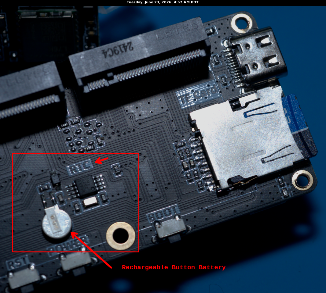
The LilyGO T-Beam Supreme has a real time clock, aka “RTC”, circuit powered by a small hidden rechargeable battery that can hold a charge for 2-3 days. If your T-Beam is without power from A) its larger battery, a 18650 Li-Ion battery or B) a powered USB connector, then your stored date and time value will be lost after 2-3 days. 7 The loss of current date and time can be easily fixed, if your firmware anticipates this condition, by fetching satellite time and synchronizing the RTC and maintaining a date-time register (memory storage). When you want to synchronize to satellite time, you do have to expose your T-Beam to several satellites by taking it outside or placing it near a window that can see several satellites. To establish its own full position-and-time solution, a GNSS receiver normally uses signals from at least four satellites. The receiver compares the transmitted timing information with when each signal arrives, solves for its own position and clock error, and then can provide an accurate timing reference.
The RTC precision is down to the second, not milliseconds. This precision should be adequate for everyday use where sub-second precision is not needed. But for testing and logging what happens within the T-Beam using Reticulum’s transport, millisecond precision of time along with synchronization of all units involved in the test is warranted. For example, if you log that AMY sends a message at 14:02:33.407 (the “407” represents milliseconds, or thousandths (407 of 1,000) of a second) and BOB logs receipt of the same transmission at 14:02:33.023, you want BOB to be in sync with AMY, otherwise a BOB log entry of 14:02:33.023 means BOB is on a different time scale. You want to see BOB receiving the message at 14:02:33.407 or later depending on how long it takes to actually transmit and then for the LoRa circuitry to demodulate the incoming message.
Thus, the goal is to have the T-Beams share the same “wall clock”8 time so that their logs match the same time as close as possible. Using the RTC stored seconds-precision is not precise enough as units could be off synchronization by as much as 1 second or more. A lot can happen in radio land during one second. Without time synchronization, correlating logs files generated by several T-Beams becomes almost impossible — you would have to know how much each unit varies from another. Therefore, one cannot rely upon the RTC to provide commonality of time among several units. For precision analysis of logs, the date and time stamps must be as synchronized as possible.
Synchronizing Time
Back in the Age of Reason, i.e. the 1960s, if you wanted to know what the current time was, you could dial 853-1212 and the telephone company would have a recording answer with “At the tone, the time will be 3:45 and 20 seconds… BEEP”. Here‘s a recreation of such a message9. When you heard the BEEP, you would know that US time was 3:45:20. You could then set your clock accordingly and feel that your clock is now synchronized close to a second. Remember, though, clocks drift, and one month from now, your clock may be off, so you could call telephone time and reset your clock. When daylight savings time would start or end, calling time was a convenient moment in the year to reset clocks. Also, at New Year’s Eve parties when midnight approached, someone could call time so everyone would know precisely when the new year started and thus set off their firecrackers with joy.
The critical component of calling telephone time is that your are fore-warned with the necessary information, e.g. “at the the tone…”, about an event which is about to occur: the BEEP, so you could have your electric clock set to the second and then when you heard the BEEP, you could power on your clock.
In sporting events, such as track and horse racing, every contestant needs to start from the same time, so instead of beeps, you have a starting gun. When everyone hears the starting gun blast, they know they can begin the race and everybody is starting from the same event: the gun blast

See the article “Monotonic Clocks and Precise Time Measurement ” for a more complex analysis of time in computer networks.
Satellite Time
The same concept as the starter gun in a track race, or the telephone company BEEP, is used in satellite time. A constellation of satellites is in the sky, they are coordinated by atomic clocks to send time signals as pulses and the GPS units on the T-Beams collects several satellite’s signals and calculates its position to determine the loss of time it takes to send the signal to the current location. This is called getting a “fix”, you usually want to have 3 or more satellite signals. In my backyard, surrounded by tall trees, I can see 12 satellites. Here’s a simplified diagram showing 6 satellites sending time signals. The satellites continuously broadcast precisely timed radio signals. Because every satellite is at a different distance, each signal reaches the receiver after a different propagation delay. The GNSS receiver solves those delays, its position, and its own clock offset. Once it has a stable solution, the receiver produces a local electrical timing signal: one pulse per second, commonly called PPS [pulse per second]. You will see in the documentation of time-related software “pps” or “PPS” commonly used.

The ESP32 has a continuously running timer that can report elapsed time with microsecond resolution. By itself, that timer will drift relative to UTC. Exercise 28 repeatedly anchors it to the GNSS receiver’s PPS edge, allowing the firmware to interpolate the microseconds between one precisely marked second and the next.
T-Beam pps Synchronized Software Clock
In a T-Beam exercise 10 each T-Beam receives a very precise “tick” from the GPS receiver once per second, called PPS—short for pulse per second. Think of it as seven runners all hearing the same starting pistol every second. The GPS messages tell the T-Beam which numbered UTC second that tick represents, while the ESP32’s own continuously running timer fills in the tiny fractions of a second until the next tick arrives. By repeatedly lining up its internal timer with these GPS second marks, each T-Beam can assign an accurate time, down to microseconds11, to events it sees or sends. The small battery-backed clock on the board is not being used as this precision clock in Exercise 28; it is only a separate, coarse clock that can retain ordinary date-and-time information when the unit is powered down.
To visualize when the PPS arrive, I have the units display for 18 milliseconds on the OLED display a “flash”. Thus, when all 7 units have stabilized their time readings, they should all be flashing at the same time. I recorded the flashing sequences using a camera that can take 59.94 frames per second. Here‘s a sample of the video.
But we must not rely on the naked eye to witness if the units are all in sync. Instead, I inspected some select frames from the video. Here is some math: $$1/59.94=16.68 ms$$
The display time I arbitrarily set for 18 ms: $$kPpsFlashMs=18 ms$$
Therefore: $$18/16.68=1.08 frames$$ which should be a sufficient strobe. Because the 18 ms flash is only slightly longer than one 16.68 ms video frame, a PPS event may appear in one frame or be divided across two adjacent frames, depending on where the camera’s frame boundary falls. The video therefore provides a useful visual check, but not a measurement at microsecond precision.
Frame Captures (59.94 fps)
| Frame | Photo Left -> Right: AMY BOB CY DAN ED FLO GUY | Comment |
|---|---|---|
| 37 | 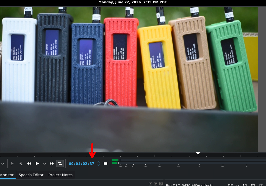 | No Strobe |
| 38 | 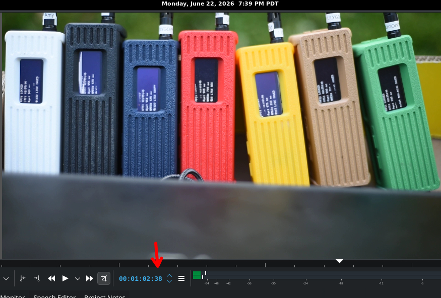 | Partial: BOB |
| 39 | 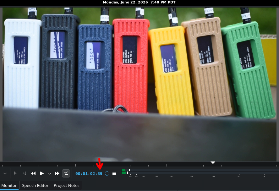 | Partial: BOB CY ED |
| 40 | 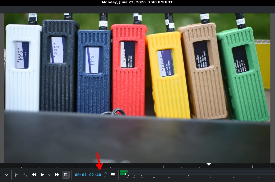 | Partials: AMY BOB CY DAN ED |
| 41 | 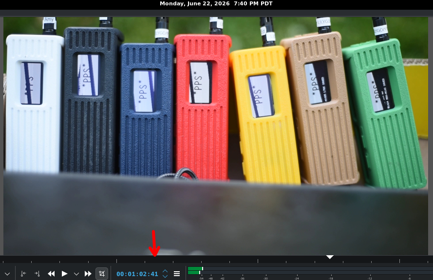 | Full: AMY BOB CY DAN ED, Partial FLO GUY |
| 42 | 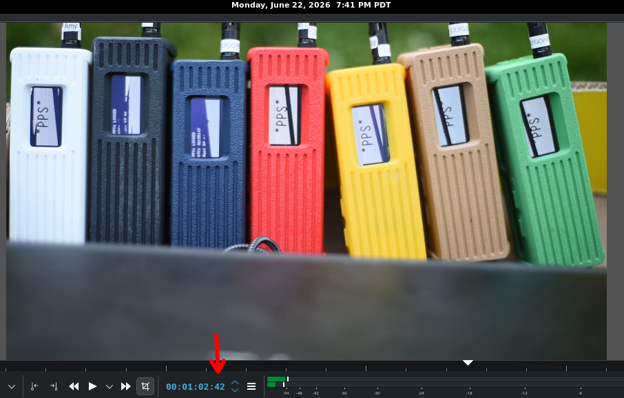 | Full: AMY DAN ED FLO GUY |
| 43 | 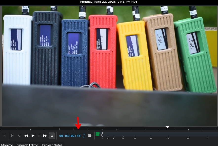 | Full: FLO GUY, Partial: AMY DAN ED |
| 44 | 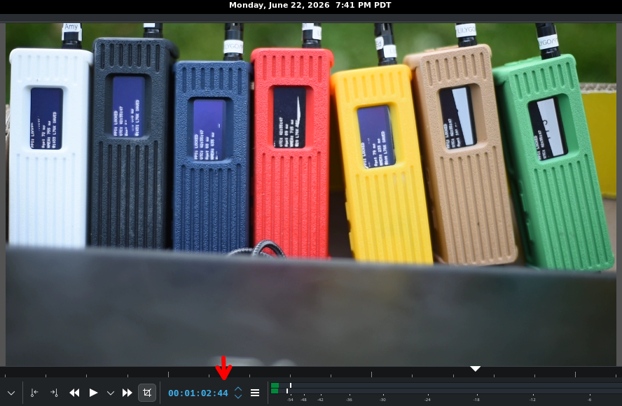 | Partial: DAN FLO GUY |
| 45 | 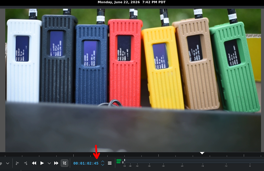 | No strobe |
Frame Capture Discussion
Ideally, I was hoping for 3 frames, 2 frames showing partials bounding a frame show all in full. Remember, each frame represents 16.68ms, so having 8 frames represents 133.44ms of time. ChatGPT cautioned that:
The practical complication: the OLED itself
An 18 ms software interval may not yield an 18 ms optical pulse if your code redraws a substantial part of the 128×64 SH1106 display over I²C.
A complete framebuffer is approximately:
128×64/8=1024 bytes128 \times 64 / 8 = 1024\text{ bytes}
At 400 kHz I²C, transferring a full framebuffer alone can take on the order of 23 ms or more, before controller commands and software overhead. Therefore, if your heartbeat implementation performs a full-display redraw for both the “on” and “off” states, an 18 ms setting may be below the practical display-update time.
That does not invalidate the experiment, but it changes what you are measuring:
You would be measuring PPS-to-visible-OLED timing, including firmware scheduling, display drawing, I²C transfer, and OLED refresh—not PPS interrupt timing alone.
For the video experiment, that may actually be exactly what you want: it shows whether the seven units present their PPS indication coherently to an observer.
I suspected all the logging activity, both via the UART and to the unit’s memory might be a factor affecting the OLED, so I built a firmware version without any logging and launched the 7 units and video recorded them. The number of frames between empty was 6; that’s an improvement, but I am still wondering why the seven T-Beams are not all appearing with full heart beats in one frame when reviewed in a video software platform where each frame can be viewed.
Conclusion re: video capture
Pretty, but not precise enough. We need more.
The Logs
In my run above where the screenshots of the frames are shown, I ran a 17-1/2 minute run and logged both on the T-Beams SRAM and over the UART port to my laptop where I have a Perl script wrap each incoming message with a high precision time code. Yes, I had 7 consoles opened. I have built a Perl script that parses both types of logs and stuffs them into a SQLite database. Having both logs in the database allows me to ask questions about various relationships of the parsed data.
With the seven T-Beams mechanically supported so that their USB-C connectors were no longer under load, all seven completed the planned 17-minute internal-PPS-flash capture capture without interruption or write errors. Each unit maintained an unbroken PPS count sequence. Comparing the PPS-disciplined microsecond clocks reported by the units through the live UART monitor showed that their central host-observed offsets occupied only a 0.166 ms span. When examined minute by minute, the seven-unit spread remained below 0.633 ms for the full run. This does not directly measure the electrical phase difference among the seven GNSS PPS outputs, but it demonstrates that the reconstructed clocks and their end-to-end reporting paths remained mutually consistent to substantially better than one millisecond.
For further details, see Achieving 166 µs Clock Synchronization Across 7 T-Beams
The Problem With RTC
The T-Beam uses an RTC circuit12 which has a quartz crystal that vibrates mechanically at approximately 32,768 cycles per second, or Herz (“Hz”). The selection of a crystal oscillating at 32,768 Hz was not by accident, but by design since 32,768 is $$2^{15}$$. Think of the crystal as a beating heart. So digital circuitry can divide by two, fifteen times to determine a second and then each one-second tick increments the RTC’s calendar registers.
32,768 Hz
16,384 Hz
8,192 Hz
...
2 Hz
1 Hz
The unavoidable issue is that its crystal is not exactly 32,768.000000 Hz under real conditions. Its frequency changes due to:
- manufacturing tolerance of the crystal;
- temperature;
- aging;
- oscillator load capacitance and board layout;
- supply conditions and electrical noise, to a lesser degree.
So the RTC can drift in time and be off. Moreover, the RTC is not meant to be a high precision component. The RTC’s calendar interface is second-resolution and is suitable for retaining ordinary date and time across a power interruption. Its quartz oscillator can drift with temperature, aging, and manufacturing tolerance, so it is not the timing source used for this sub-millisecond synchronization experiment.
(I acknowledge that the footnotes have problems, that’s on WordPress and Easy Footnotes — standard edition.)
- See <a href="https://github.com/Xinyuan-LilyGO/LilyGo-LoRa-Series/issues/300#issuecomment-4641606721">Issue #300</a> “External RTC backup battery present but undocumented / missing from specifications and schematic”. The photo is of the side opposite of the main battery circuit board; this region is hidden by the second circuit board, removed for this photograph, that contains the ESP32-S module and is plugged into the 2 connectors. The button battery, Seiko 3V 5.5mAh, is not meant to be serviceable, see <a href="https://github.com/Xinyuan-LilyGO/LilyGo-LoRa-Series/issues/300#issuecomment-4310386357">comment</a> of LewisHe.
- “Wall clock” refers to a clock on the wall that everyone sees. For example, in a classroom, every student has a watch, but their watches tell different times. So to assure uniformity, the students are instructed to reference the clock on the wall as the official time source. “Pencils down (a phrase meaning stop writing your exam essay) at 3:00 p.m.” means what the wall clock says, not your own watch says or what you would have it say.
- And for the romantics reading this, <a href="https://salemdata.net/time_french_20260622_1546_beep.wav">here</a>‘s a version in French.
- Exercise <a href="https://salemdata.net/repo/jlpoole/microReticulumTbeam/src/branch/feature/fieldtest-beacon-sd-provision/exercises/28_GNSS_PPS_Clock">28_GNSS_PPS_Clock</a>
- Microseconds = .000001 or one <b>millionth</b> (1/1,000,000) of a second. Often denoted by the symbol: μ (the Greek letter <a title="Mu (letter)" href="https://en.wikipedia.org/wiki/Mu_(letter)">mu</a>).
- The RTC component is a <strong data-start="4" data-end="67">NXP PCF85063ATL</strong>
- See Issue #300 “External RTC backup battery present but undocumented / missing from specifications and schematic”. The photo is of the side opposite of the main battery circuit board; this region is hidden by the second circuit board, removed for this photograph, that contains the ESP32-S module and is plugged into the 2 connectors. The button battery, Seiko 3V 5.5mAh, is not meant to be serviceable, see comment of LewisHe.
- “Wall clock” refers to a clock on the wall that everyone sees. For example, in a classroom, every student has a watch, but their watches tell different times. So to assure uniformity, the students are instructed to reference the clock on the wall as the official time source. “Pencils down (a phrase meaning stop writing your exam essay) at 3:00 p.m.” means what the wall clock says, not your own watch says or what you would have it say.
- And for the romantics reading this, here‘s a version in French.
- Exercise 28_GNSS_PPS_Clock
- Microseconds = .000001 or one millionth (1/1,000,000) of a second. Often denoted by the symbol: μ (the Greek letter mu).
- The RTC component is a NXP PCF85063ATL
Leave a Reply