<p><strong>Technical / DIY</strong> — for those interested in do-it-yourself sound monitoring of hyperscale data centers and related circuitry</p>
<p>I’ve been mulling over Preston Blackburn’s Remote Audio Monitor design (see <a href="https://salemdata.net/johnpress/?p=1223">Monitor Sounds From a Data Center?</a>) and assessing its ability to monitor infrasound (<20hz) and low frequencies between 20 Hz and 50 Hz. Blackburn uses the MEMS Microphone Breakout – ICS-43434. The project Blackburn references, “Low-cost solar-powered urban soundscape sensor” also used the ICS-43434. Adafruit sells an I2S MEMS Microphone Breakout – ICS-43434, <a href="https://www.adafruit.com/product/6049">Product ID: 6049.</a> The problem is that the ICS-43434 microphone is not good for low frequency sounds, Adafruit notes its limitation:</p>
<blockquote><p>a range of about 50Hz – 15KHz, good for all general audio recording/detection.</p></blockquote>
<p>So the above limitations work <em>against</em> trying to capture and monitor sounds below 50 Hz. I worked with ChatGPT and identified four other MEMS microphones to see what their frequency ranges are. Here is a table of my findings followed by notes specific to a particular model</p>
<h3>Comparison Table Standardized</h3>
<div style="overflow-x: auto;">
<table style="min-width: 1100px;">
<thead>
<tr>
<th>Microphone</th>
<th style="text-align: right;">100 Hz</th>
<th style="text-align: right;">63 Hz</th>
<th style="text-align: right;">50 Hz</th>
<th style="text-align: right;">40 Hz</th>
<th style="text-align: right;">31.5 Hz</th>
<th style="text-align: right;">25 Hz</th>
<th style="text-align: right;">20 Hz</th>
<th style="text-align: right;">15 Hz</th>
<th style="text-align: right;">10 Hz</th>
<th style="text-align: right;">5 Hz</th>
</tr>
</thead>
<tbody>
<tr>
<td>ICS-43434</td>
<td style="text-align: right;">~-1 dB [G]</td>
<td style="text-align: right;">~-3 dB [G]</td>
<td style="text-align: right;">~-5 dB [G]</td>
<td style="text-align: right;">~-7 dB [G]</td>
<td style="text-align: right;">~-10 dB [G]</td>
<td style="text-align: right;">~-13 dB [G]</td>
<td style="text-align: right;">~-15 dB [G]</td>
<td style="text-align: right;">~-20 dB [G]</td>
<td style="text-align: right;">~-25 dB [G]</td>
<td style="text-align: right;">N/P</td>
</tr>
<tr>
<td>T5838</td>
<td style="text-align: right;">~0 dB [G]</td>
<td style="text-align: right;">~0 dB [G]</td>
<td style="text-align: right;">~-1 dB [G]</td>
<td style="text-align: right;">~-1 dB [G]</td>
<td style="text-align: right;">~-2 dB [G]</td>
<td style="text-align: right;">~-3 dB [G]</td>
<td style="text-align: right;">~-5 dB [G]</td>
<td style="text-align: right;">~-8 dB [G]</td>
<td style="text-align: right;">~-13 dB [G]</td>
<td style="text-align: right;">N/P</td>
</tr>
<tr>
<td>IM73D122V01</td>
<td style="text-align: right;">~-0.5 dB [G]</td>
<td style="text-align: right;">~-0.5 dB [G]</td>
<td style="text-align: right;">~-1 dB [G]</td>
<td style="text-align: right;">~-1.5 dB [G]</td>
<td style="text-align: right;">~-1.5 dB [G]</td>
<td style="text-align: right;">~-2.5 dB [G]</td>
<td style="text-align: right;">-3.0 dB [S]</td>
<td style="text-align: right;">N/S</td>
<td style="text-align: right;">N/S</td>
<td style="text-align: right;">N/P</td>
</tr>
<tr>
<td>IM73A135V01</td>
<td style="text-align: right;">~0 dB [G]</td>
<td style="text-align: right;">~-0.5 dB [G]</td>
<td style="text-align: right;">~-1 dB [G]</td>
<td style="text-align: right;">~-1 dB [G]</td>
<td style="text-align: right;">~-1.5 dB [G]</td>
<td style="text-align: right;">~-2 dB [G]</td>
<td style="text-align: right;">-3.0 dB [S]</td>
<td style="text-align: right;">N/P</td>
<td style="text-align: right;">N/P</td>
<td style="text-align: right;">N/P</td>
</tr>
<tr>
<td>MP23ABS1</td>
<td style="text-align: right;">~0 dB [G]</td>
<td style="text-align: right;">~0 dB [G]</td>
<td style="text-align: right;">~-1 dB [G]</td>
<td style="text-align: right;">~-1 dB [G]</td>
<td style="text-align: right;">~-1 dB [G]</td>
<td style="text-align: right;">~-2 dB [G]</td>
<td style="text-align: right;">~-2 dB [G]</td>
<td style="text-align: right;">N/P</td>
<td style="text-align: right;">N/P</td>
<td style="text-align: right;">N/P</td>
</tr>
</tbody>
</table>
</div>
<p><strong>43434</strong> Notes: [S]: None of the requested frequencies has an explicit manufacturer-stated relative response value.<br />
[G]: 100 Hz, 63 Hz, 50 Hz, 40 Hz, 31.5 Hz, 25 Hz, 20 Hz, 15 Hz, and 10 Hz.<br />
Response curve: Datasheet page 11, Figure 4, “Typical Frequency Response (Measured).”<br />
Uncertainty: Values are approximate visual readings from the logarithmic graph. The curve is relatively small and has 10 dB vertical grid spacing, so estimates below 100 Hz should be treated as approximate. The graph begins at 10 Hz, so 5 Hz is N/P.</p>
<p><strong>T5838</strong> Notes: [S] cells: none. The datasheet specifies -3 dB low-frequency roll-off at 27 Hz, but 27 Hz is not one of the requested frequencies, so it was not converted into a requested-frequency value. [G] cells: 100 Hz, 63 Hz, 50 Hz, 40 Hz, 31.5 Hz, 25 Hz, 20 Hz, 15 Hz, and 10 Hz. Response curve: datasheet page 12, Figure 4, “Typical Audio Frequency Response, High Quality Mode.” The graph is logarithmic and relatively small, so values below about 50 Hz are approximate visual readings; 5 Hz is outside the plotted frequency range.</p>
<p><strong>IM73D122V01</strong> Notes: [S] 20 Hz is manufacturer-specified as the low-frequency roll-off at -3 dB relative to 1 kHz. [G] 100, 63, 50, 40, 31.5, and 25 Hz are estimated from the manufacturer’s typical amplitude-response curve. Response curve: datasheet page 4, Figure 2, “Typical amplitude response.” The plotted response trace begins at about 20 Hz, so although 10 Hz and 15 Hz fall within the graph’s displayed frequency-axis range, no response trace is provided there; these are therefore N/S rather than graph-derived estimates. 5 Hz is outside the displayed graph range and is N/P. Graph readings are approximate because Figure 2 has 3 dB vertical grid spacing and does not provide numeric values at the intermediate frequencies. Source: Infineon IM73D122V01 datasheet, version 1.00, 2022-08-12.</p>
<p><strong>IM73A135V01</strong> Notes: [S]: 20 Hz. The manufacturer specifies the low-frequency cutoff point as 20 Hz at -3 dB relative to 1 kHz.</p>
<p>[G]: 100 Hz, 63 Hz, 50 Hz, 40 Hz, 31.5 Hz, and 25 Hz are approximate readings from the typical amplitude-response curve.</p>
<p>Response curve: Datasheet page 4, Figure 2, “Typical amplitude response.” Page 7, Figure 10 provides upper and lower free-field response limits but does not provide a typical response trace suitable for assigning exact response values to these cells.</p>
<p>Uncertainty: Figure 2 is small and has coarse 3 dB vertical divisions, so graph-derived values are intentionally rounded. The plotted response begins at about 20 Hz; no response trace is provided at 15 Hz, 10 Hz, or 5 Hz.</p>
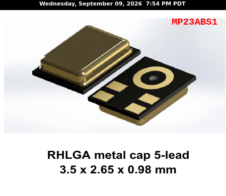
<p><strong>MP23ABS1</strong> Notes: No requested-frequency cells are manufacturer-specified [S]. The 35 Hz and 100 Hz entries in Table 4 are response-mask limits, not exact response values, so they are not treated as [S] values. The 100 Hz through 20 Hz cells are graph-derived [G] from datasheet page 5, Figure 2, “Typical free-field frequency response normalized at 1 kHz.” The curve is relatively thick and the logarithmic frequency axis has limited low-frequency resolution, so estimates are intentionally rounded to whole dB. The plotted response curve begins at about 20 Hz; therefore 15 Hz, 10 Hz, and 5 Hz are reported as N/P rather than extrapolated.</p>
<p>At this point, I’m wondering if it might be worthwhile to produce a run of evaluation/breakout boards just like Adafruit has for each of the other four microphones. If you are interested in sharing the fabrication cost of a small PCB run. so you can test the microphones without having to fuss with surface mount soldering and placement, please contact me. <em>Note:</em> such Adafruit-like breakout boards for all these microphones may be uniform in theirs pins, but they will not necessarily be electrically interchangeable. Different microphones may require different supply decoupling, output/interface circuitry, footprints, clocking, or analog versus digital handling.</p>
<p>I welcome anyone with <strong data-start="2031" data-end="2113">PCB design, acoustics, DSP, ESP32, calibration, or field-monitoring experience</strong>.</p>
Technical / DIY — for those interested in do-it-yourself sound monitoring of hyperscale data centers and related circuitry
I’ve been mulling over Preston Blackburn’s Remote Audio Monitor design (see Monitor Sounds From a Data Center?) and assessing its ability to monitor infrasound (<20hz) and low frequencies between 20 Hz and 50 Hz. Blackburn uses the MEMS Microphone Breakout – ICS-43434. The project Blackburn references, “Low-cost solar-powered urban soundscape sensor” also used the ICS-43434. Adafruit sells an I2S MEMS Microphone Breakout – ICS-43434, Product ID: 6049. The problem is that the ICS-43434 microphone is not good for low frequency sounds, Adafruit notes its limitation:
a range of about 50Hz – 15KHz, good for all general audio recording/detection.
So the above limitations work against trying to capture and monitor sounds below 50 Hz. I worked with ChatGPT and identified four other MEMS microphones to see what their frequency ranges are. Here is a table of my findings followed by notes specific to a particular model
Comparison Table Standardized
| Microphone |
100 Hz |
63 Hz |
50 Hz |
40 Hz |
31.5 Hz |
25 Hz |
20 Hz |
15 Hz |
10 Hz |
5 Hz |
| ICS-43434 |
~-1 dB [G] |
~-3 dB [G] |
~-5 dB [G] |
~-7 dB [G] |
~-10 dB [G] |
~-13 dB [G] |
~-15 dB [G] |
~-20 dB [G] |
~-25 dB [G] |
N/P |
| T5838 |
~0 dB [G] |
~0 dB [G] |
~-1 dB [G] |
~-1 dB [G] |
~-2 dB [G] |
~-3 dB [G] |
~-5 dB [G] |
~-8 dB [G] |
~-13 dB [G] |
N/P |
| IM73D122V01 |
~-0.5 dB [G] |
~-0.5 dB [G] |
~-1 dB [G] |
~-1.5 dB [G] |
~-1.5 dB [G] |
~-2.5 dB [G] |
-3.0 dB [S] |
N/S |
N/S |
N/P |
| IM73A135V01 |
~0 dB [G] |
~-0.5 dB [G] |
~-1 dB [G] |
~-1 dB [G] |
~-1.5 dB [G] |
~-2 dB [G] |
-3.0 dB [S] |
N/P |
N/P |
N/P |
| MP23ABS1 |
~0 dB [G] |
~0 dB [G] |
~-1 dB [G] |
~-1 dB [G] |
~-1 dB [G] |
~-2 dB [G] |
~-2 dB [G] |
N/P |
N/P |
N/P |
43434 Notes: [S]: None of the requested frequencies has an explicit manufacturer-stated relative response value.
[G]: 100 Hz, 63 Hz, 50 Hz, 40 Hz, 31.5 Hz, 25 Hz, 20 Hz, 15 Hz, and 10 Hz.
Response curve: Datasheet page 11, Figure 4, “Typical Frequency Response (Measured).”
Uncertainty: Values are approximate visual readings from the logarithmic graph. The curve is relatively small and has 10 dB vertical grid spacing, so estimates below 100 Hz should be treated as approximate. The graph begins at 10 Hz, so 5 Hz is N/P.
T5838 Notes: [S] cells: none. The datasheet specifies -3 dB low-frequency roll-off at 27 Hz, but 27 Hz is not one of the requested frequencies, so it was not converted into a requested-frequency value. [G] cells: 100 Hz, 63 Hz, 50 Hz, 40 Hz, 31.5 Hz, 25 Hz, 20 Hz, 15 Hz, and 10 Hz. Response curve: datasheet page 12, Figure 4, “Typical Audio Frequency Response, High Quality Mode.” The graph is logarithmic and relatively small, so values below about 50 Hz are approximate visual readings; 5 Hz is outside the plotted frequency range.
IM73D122V01 Notes: [S] 20 Hz is manufacturer-specified as the low-frequency roll-off at -3 dB relative to 1 kHz. [G] 100, 63, 50, 40, 31.5, and 25 Hz are estimated from the manufacturer’s typical amplitude-response curve. Response curve: datasheet page 4, Figure 2, “Typical amplitude response.” The plotted response trace begins at about 20 Hz, so although 10 Hz and 15 Hz fall within the graph’s displayed frequency-axis range, no response trace is provided there; these are therefore N/S rather than graph-derived estimates. 5 Hz is outside the displayed graph range and is N/P. Graph readings are approximate because Figure 2 has 3 dB vertical grid spacing and does not provide numeric values at the intermediate frequencies. Source: Infineon IM73D122V01 datasheet, version 1.00, 2022-08-12.
IM73A135V01 Notes: [S]: 20 Hz. The manufacturer specifies the low-frequency cutoff point as 20 Hz at -3 dB relative to 1 kHz.
[G]: 100 Hz, 63 Hz, 50 Hz, 40 Hz, 31.5 Hz, and 25 Hz are approximate readings from the typical amplitude-response curve.
Response curve: Datasheet page 4, Figure 2, “Typical amplitude response.” Page 7, Figure 10 provides upper and lower free-field response limits but does not provide a typical response trace suitable for assigning exact response values to these cells.
Uncertainty: Figure 2 is small and has coarse 3 dB vertical divisions, so graph-derived values are intentionally rounded. The plotted response begins at about 20 Hz; no response trace is provided at 15 Hz, 10 Hz, or 5 Hz.
MP23ABS1 Notes: No requested-frequency cells are manufacturer-specified [S]. The 35 Hz and 100 Hz entries in Table 4 are response-mask limits, not exact response values, so they are not treated as [S] values. The 100 Hz through 20 Hz cells are graph-derived [G] from datasheet page 5, Figure 2, “Typical free-field frequency response normalized at 1 kHz.” The curve is relatively thick and the logarithmic frequency axis has limited low-frequency resolution, so estimates are intentionally rounded to whole dB. The plotted response curve begins at about 20 Hz; therefore 15 Hz, 10 Hz, and 5 Hz are reported as N/P rather than extrapolated.
At this point, I’m wondering if it might be worthwhile to produce a run of evaluation/breakout boards just like Adafruit has for each of the other four microphones. If you are interested in sharing the fabrication cost of a small PCB run. so you can test the microphones without having to fuss with surface mount soldering and placement, please contact me. Note: such Adafruit-like breakout boards for all these microphones may be uniform in theirs pins, but they will not necessarily be electrically interchangeable. Different microphones may require different supply decoupling, output/interface circuitry, footprints, clocking, or analog versus digital handling.
I welcome anyone with PCB design, acoustics, DSP, ESP32, calibration, or field-monitoring experience.
Leave a Reply